3D metrology in moulded components
Progress indicator
Moulded component manufacture presents several challenges for quality professionals because of component types, manufacturing techniques and base materials. Derek Scott CQP FCQI argues that contactless 3D measurement is a superior strategy for industrial engineers working in this field.
Using a point contact measurement strategy for moulded components is, I contend, fundamentally flawed – and the problem is exacerbated as the materials from which moulded components are made become progressively softer.
Issues with the approach primarily relate to the increased opportunity for measurement error or inaccuracy when touching a part, because of the deformation this induces. Deformation can be brought about by application of the measurement itself – for example, over-zealous hand-tool use or poor coordinate measuring machine (CMM) programming – or by manipulating parts inappropriately to fit them to a pre-existing measurement fixture.
An additional factor that should be considered is the relative lack of information that a point contact measurement approach yields. A linear height measurement taken with a set of callipers, for example, will give you a measurement from top to bottom of the part in that exact linear direction and between those two points only. Moving the callipers to other points on the part will yield different results.
Variation in these results will depend on factors such as: the repeatability and reproducibility of the system doing the measuring; the fineness requirements of the measurement; and the capability of the mould/material/process making up the part.
This problem can be addressed somewhat by taking more measurements and averaging them, to try to reduce the relative measurement error. However, this approach still depends on the above-mentioned factors, so is liable to have similar deficiencies. No amount of measurements with a broken instrument will yield a result reflective of the ‘true value’ of the measurand.
Further, mouldable materials have allowable percentages of shrinkages that engineers must consider. Some parts may be moulded from dissimilar materials with different shrinkage rates in a single component assembly – so shrinkage in the mould may be unevenly distributed across the part. Point contact measurement is a poor and inefficient detective for this, with a great many measurements having to be taken to build a truly reflective picture of the part under investigation. This leads to expensive and time-consuming inspections, the results of which cannot be truly relied upon.
Process monitoring challenges
The unreliability of results from point contact measurement extends to factors such as ultimate product release and the possibility of accepting bad product as good, or vice versa. This will effect a business’s internal rejection rate, customer satisfaction levels and financial return.
There are also challenges with monitoring process results, adding uncertainty to the process engineer’s capability ratio calculations.
Taking the example of symmetrical moulded part(s), a simple problem is the orientation of the part(s) during measurement. This may be solved by including a moulded key in the tool, but unless you mould in multiple keys to match your measurement points, you will have an issue locating your measurement points in a precise fashion.
For example, are you measuring the outer diameter (OD)/inner diameter (ID)/height/length in the same locations as you did last time and so producing a result representative of that location? If not, you may produce capability metrics or control charts made up of data from regions of the part that are intrinsically dissimilar to each other, though this may be unknown to you.
Additionally, materials with dissimilar shrinkage rates in a single component – and, potentially, tools with heat and pressure distributed dissimilarly throughout their entire body – mean that industrial engineers will be particularly challenged to produce monitoring results that can be said to be statistically representative of the mould/material/process as a whole.
Superior adaptations of traditional technologies
This uncertainty can be improved upon – to a degree. Well-written measurement specifications and parts marked for the geometry relative to the moulding tool will help; control over process inputs is also a must for reliable process outputs.
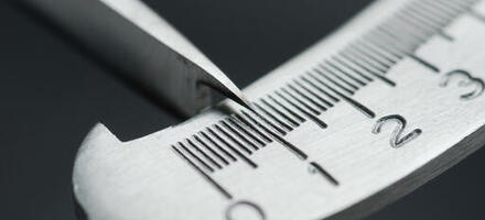
Technological adaptions for point contact measurement in this field are also available, including constant-force hand tools that show the operator how much pressure they should apply for an adequate result (see Figure 1).

Figure 1 - Example of constant-force point contact measurement callipers
Soft-force probes that provide for a greater degree of sensitivity than standard probes can also be sought for CMMs.
More sensitive and reliable tools do not, however, eliminate the fundamental challenges listed above; they simply mitigate some of the uncertainty of a flawed approach.
3D metrology solutions
An alternative approach to point contact measurement must clearly be a form of contactless measurement.
Vision camera systems have their place, but also have limitations in determining geometries of parts, as they are often restricted to 2D measurement. This is acceptable if you wish to take a series of measurements from a bird’s eye view on a tray of parts, and their rates of return for results are presently unmatched by most 3D systems. However, it is less acceptable if you wish to determine the angles on the sides or the internals of a part.
"Quality professionals and engineers working in the field of moulded components, particularly those requiring fine levels of metrology with the greatest degree of insight, should seriously consider using 3D metrology."
Shadowgraphs and putty impressions are options for internals or angle measurement, but will only give snapshot ‘slice’ indicators of parts. Our example of a cylinder with a groove in it – or multiple grooves in ID and OD – must have many impressions taken, or many parts destroyed, to provide a representative sample of the results of the process under investigation.
There is no such problem with 3D laser scanning. This takes many tens of thousands of datapoints per square inch to provide comprehensive data coverage, as well as technology-driven improvements that eliminate or mitigate many of the drawbacks of traditional point contact measurement strategies.
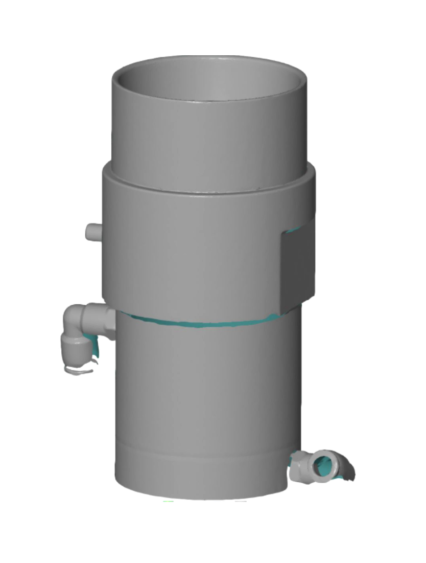
Figure 2 – Simple data mesh of cylindrical object
By building up a ‘point cloud’ of these measurements, a data mesh can be created, which can then be mapped to the original intended dimensions via the engineer’s CAD model. The creation of a ‘heat map’ image will allow the operator to identify where, and to what extent, the part deviates from desired outcomes.
By providing this information in a visual format across a fully rotatable 3D model, it is feasible to evaluate any point on a component, allowing the outcomes from a mould/material/process to be truly evaluated.
Much like a CMM, 3D metrology allows you to take measurements from the same points in space in a reliably repeatable fashion. Unlike a CMM, however, deformation from the touch of a probe is eliminated.
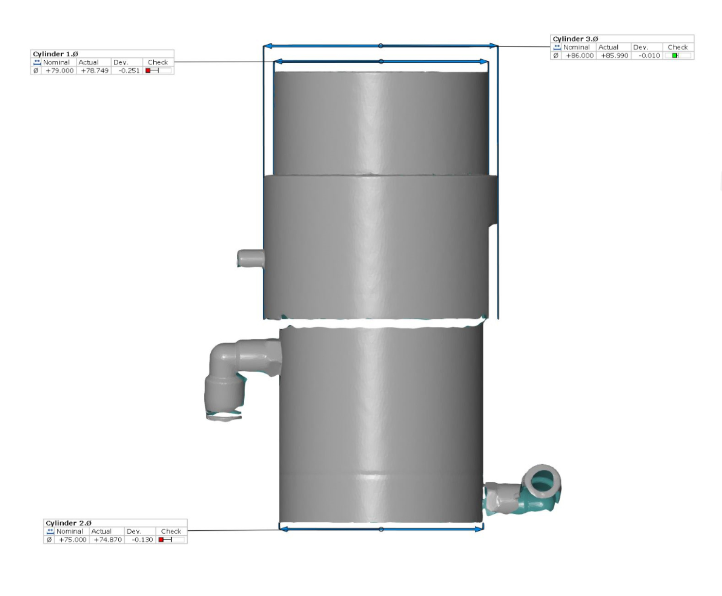
Figure 3 – Data mesh showing ‘Virtual Callipers’ taking measurements
Problem and process behaviour investigation improvements
Where deviations are identified, these can be mapped on the tool as part of problem-cause investigations – a bulge in the OD can be traced and mapped against a scan taken of the internals of the mould tool, allowing the two to be married up and conclusions drawn. The same mapping approach can be used for other dimensional characteristics and defects – eg, bowing of longer surfaces – giving deeper insight than simple point contact measurement.
Minimisation of location error can also apply to process control. A control chart monitoring a particular dimension will have its input data drawn from source more consistently. However, heat maps allow process behaviour to be viewed in new ways, with deviations from preceding measurements displayed. This allows the movement of the process to be viewed across the entirety of the part and its extent in each location assessed.
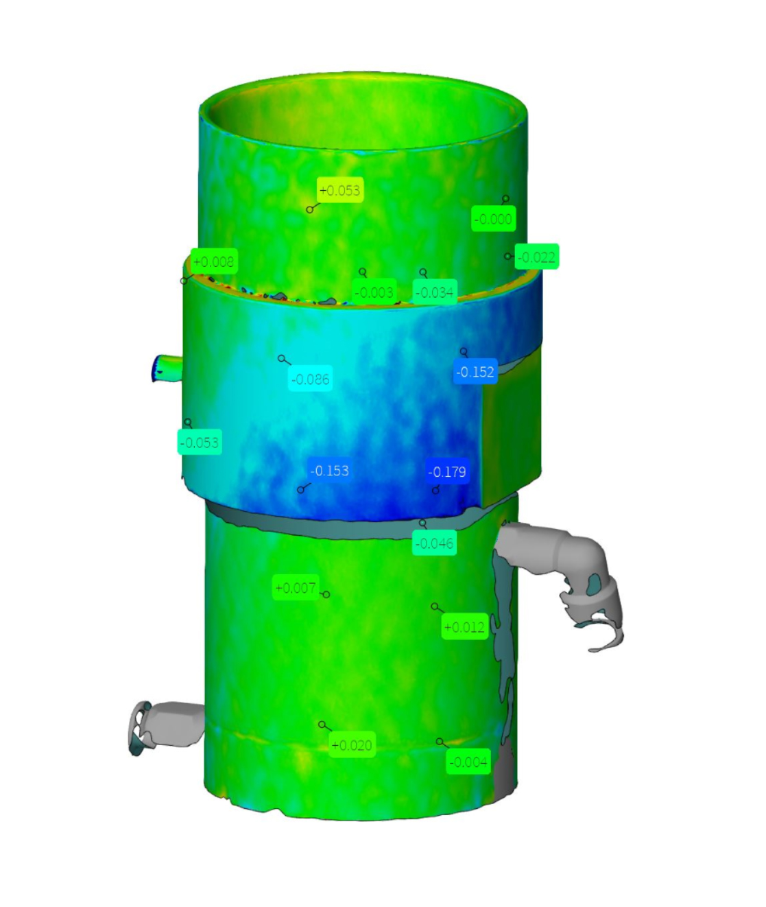
Figure 4 – Heat map showing deviations
Summary
Quality professionals and engineers working in the field of moulded components, particularly those requiring fine levels of metrology with the greatest degree of insight, should seriously consider using 3D metrology. As the arguments above have hopefully demonstrated, this technique far exceeds traditional approaches in all respects.
Acknowledgement: Figures and mesh examples provided by T3DMC, the 3D Measurement Company
Discover more great content in our Quality Learning Hub.
Brush up your skills and explore new themes in the CQI's Quality Learning Hub
Quality World

Get the latest news, interviews and features on quality in our industry leading magazine.
Become an event partner for Quality Live 2025
Raise your organisation's profile with our audience of international quality and auditing professionals
